
During my initial experimentation with projection methods, I encountered an issue when attempting to perform a coverage projection on the inside of a sphere (skydome).
The perspective distortion created a small area in the overlap area (top and bottom) where coverage was missing.

We can see the result in the display area

I explored the use of the Overscan property in the Scanline Renderer, which The Foundry, makers of Nuke, refer to as a way to control the maximum additional pixels to render beyond the left/right and top/bottom of the frame. They argue that this property can be useful where it is necessary to render pixels beyond the edges of the frame.
https://learn.foundry.com/nuke/content/reference_guide/3d_nodes/scanlinerender.html – Found on Nuke Online Help 8th Aug 19 at 08:04
I have used this before when using other nodes (i.e. lens distortion, blur etc.) where these need to have access to pixels beyond the boundaries of the display area.
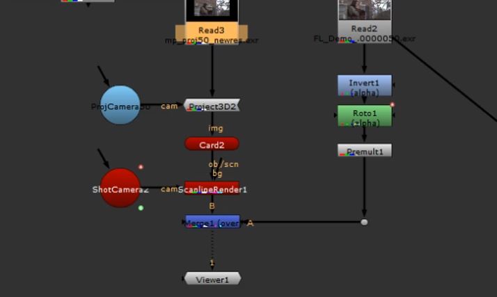
The image below shows the coverage projection with an Overscan value of 50 applied in the Scanline Renderer.
The image below shows the coverage projection with an Overscan value of 50 applied in the Scanline Renderer
The ‘marching ants’ shows an increase of the bounding box but no expansion of the actual coverage. This property extends the reach for other nodes to affect pixels which may exist beyond the display boundary. However this does not increase the resolution of the existing image.


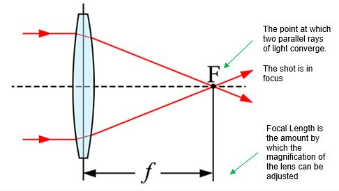
My next property for investigation was the focal length of the shot camera. My understanding, based on previous knowledge and experience of using cameras, is that this is determined by the distance between the lens and the image sensor when the subject is in focus.
https://www.howtogeek.com/353144/what-is-focal-length/
As focal length changes, the amount of the subject captured by the lens (the viewing angle) also changes.

https://av.jpn.support.panasonic.com/support/global/cs/dsc/knowhow/knowhow12.html
Of course this relates to the mechanical pieces and function of a physical camera and consequently, does not have an obvious relevance when working with computer-generated cameras.
I regard this as knowledge that is widely held, and largely unrelated, so do not want to draw this into my study. I prefer to offer an interpretation of how focal length works in the context of the CG camera and focus on the relationship between this and the projection methodologies.
When considering focal length as an attribute in a computer-generated camera, a more relevant definition would be something that controls the ‘angle of view’ or ‘how much/little we see in the display area from the perspective of the camera lens.’
To apply this theory, it is logical that increasing the focal length would have the effect of increasing the camera’s level of magnification and therefore provide Overscan.
As proof of concept, I increased the focal length value, of the shot camera, from 50 to 53

The consequence was indeed a small increase in magnification, which served to shift the areas of non-coverage beyond the display area.

Whilst this has fixed the issue on hand, my instincts tell me this is unscientific and could potentially create additional problems, particularly relating to image resolution.
Further investigation and experimentation is therefore necessary.
Understanding Overscan
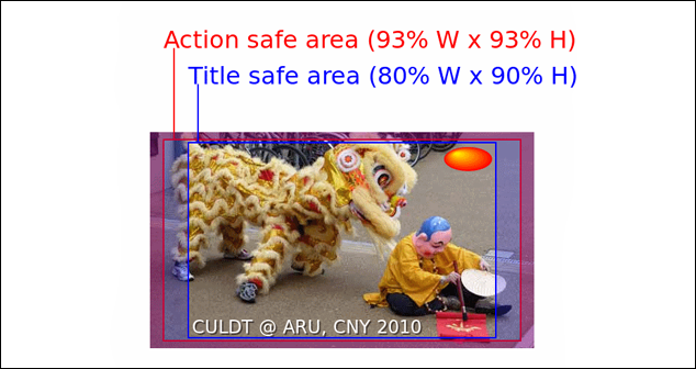
Overscan relates to pixels, which are outside the boundaries of the display area.
Most of us lived through the transition from CRT to LCD televisions and the (associated) shift from 4:3 to 16:9 aspect ratio displays.
We associate with the concept of the overscanned image from the content within the title-safe, and action-safe areas, that were not visible on a 4:3 screen.
https://www.howtogeek.com/252193/hdtv-overscan-what-it-is-and-why-you-should-probably-turn-it-off/
On modern “fixed-pixel” high-definition televisions, like LCDs, Overscan is unnecessary for final display, and is even regarded as undesirable as it can degrade the image quality.
However for the matte painter, this provides the scope to project additional content, which may not be visible initially, but appears as a consequence of a movement, or optical shift, in the shot camera.
I want to discuss this further.
Coverage to Support an Animated Shot Camera
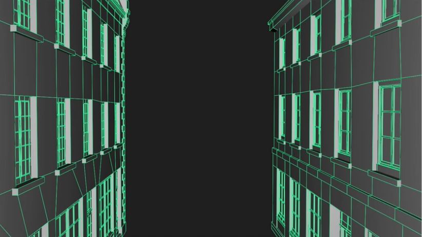
If we are moving the shot camera, then a large part of the actual image exists outside the display area but, at some point in the sequence, will be seen so must be processed by the software.
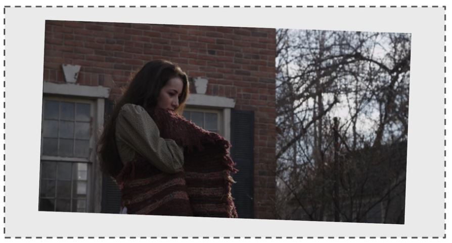
In the image below, we see a coverage projection setup depicting a camera panning up from the woman holding a blanket, up to the upstairs windows, both images would need Overscan so there is sufficient overlap to perform a blend.

Provision for Camera Shake
We should also consider more subtle movement. For example a static shot, taken in an external environment, may be subject of a small amount of camera shake.
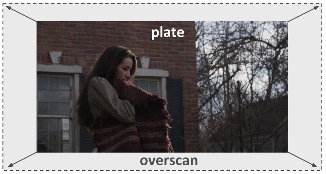
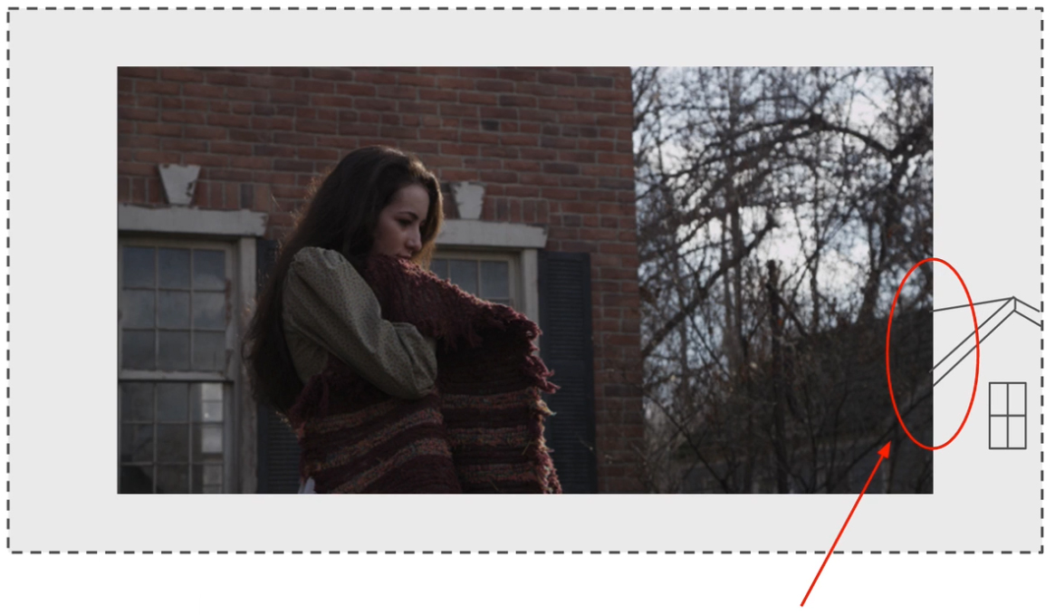
In the image (below) let’s say we have a matte painting (depicted by the dotted line) that has been made to the exact size of the plate footage.
In the image (below) I have emulated movement of the camera, which is typical in windy conditions, shooting on unstable surfaces or shooting hand-held.
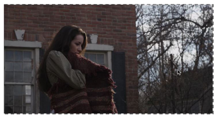
We can see that if the plate moves around, no matter how minimally, then the boundary of our matte painting is going to be visible to the viewer.
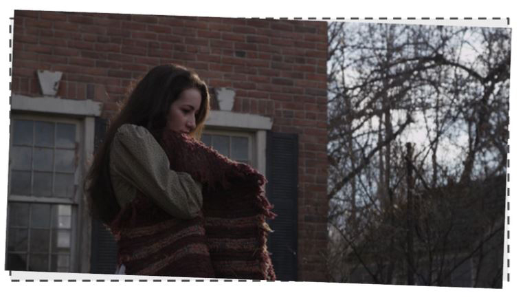
This is prevented if our matte painting is larger than the plate because there is pixel information sitting outside of the display area but, by tracking the shot, will come into frame to fill the gaps cause by the camera movement.
It therefore follows that the matte painting is created to be larger than the display area or larger than the plate footage on which the matte painting is being projected.
Minimising Projection Artefacts
A final reason for adjusting the focal length is to minimise the doubling and smearing projection artefacts.
The diagram (below) is an orthographic (top-down) depiction of a camera passing between two buildings.
This shows a choice of two focal lengths:
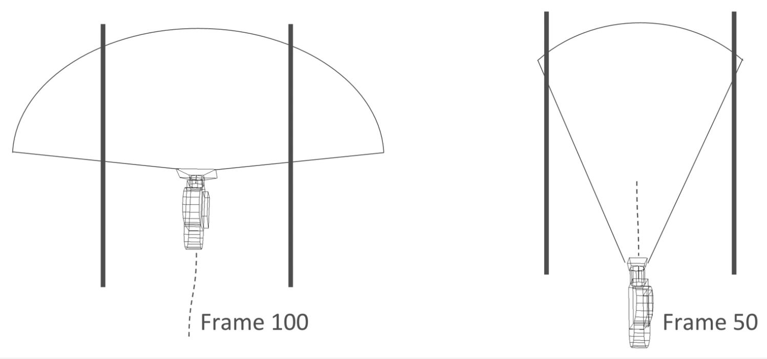
Starting with the rightmost image, the shot camera has been stopped at frame 50 (let’s say half way along its line of travel) and the focal length opened up just enough to give a small area of Overscan. The camera has a longer but narrower focal length.
Alternatively, in the left-most image, the camera is stopped at frame 100 (let’s say this is the final frame in the motion path) and the focal length opened up quite extremely to give lots of Overscan. Here the camera has a longer but narrower focal length.
The image (below) is the render from the camera with the extreme wide focal length:
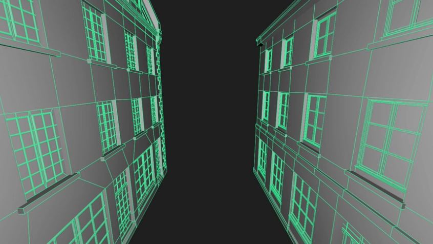
Because the angle is so wide, we get a great view of the sills and recesses of the windows.
Alternatively the image (below) shows the render from the camera with the narrower focal length:
Now we don’t get such a good view of the sills and recesses. Indeed, if we look at the closest window, part of the pane is not visible.
We know that this would translate into a much greater degree of stretching and smearing of the texture than the version with a wide focal length.
Matching the Plate to the Overscan
When opening the focal length to create Overscan, it is essential that we accurately match what is in the plate with what is in the Overscan?
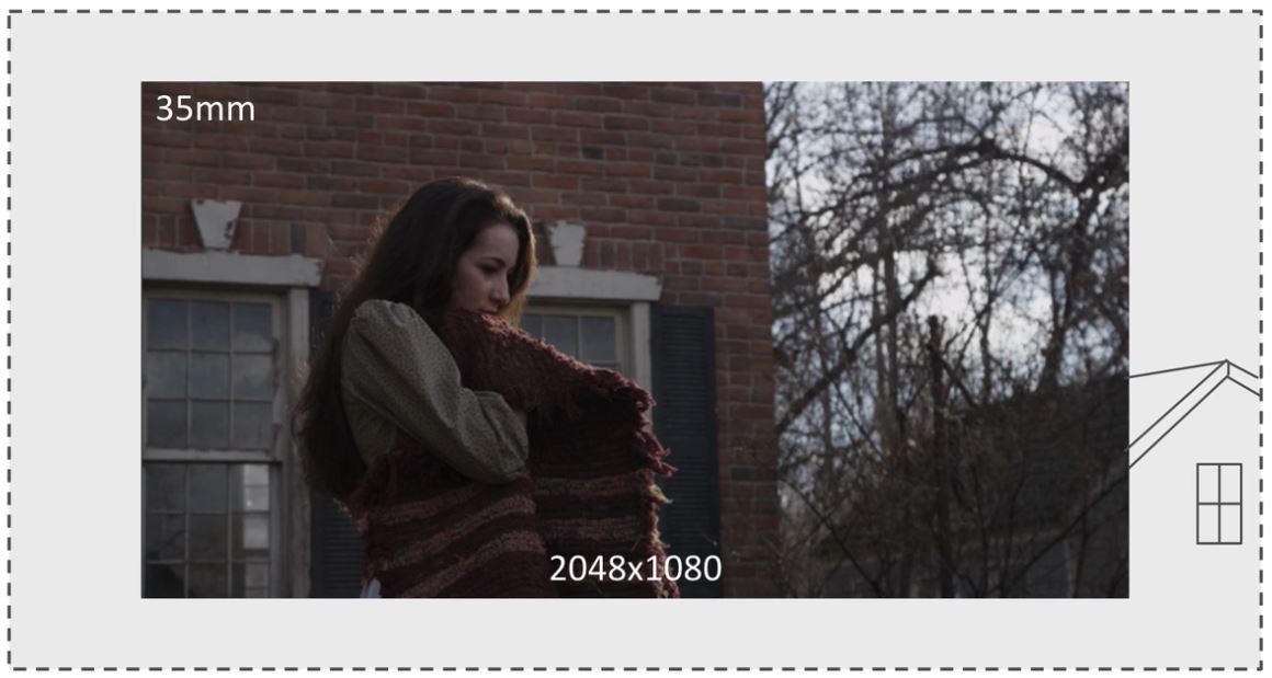
To demonstrate the calculation, I will use the image (below) as part of a scenario
Let’s say that the footage is the plate and the dotted line is the matte painting with the Overscan.

In this scenario, the camera is going to pan to the left and, in doing so, exposing more of the house on the right:

So the role of our matte painting will be to extend the house on the right.
The calculation is important because we need to ensure that, whatever we paint into our matte painting in the Overscan area, lines up exactly with the plate.
Calculating Focal Length and Resolution
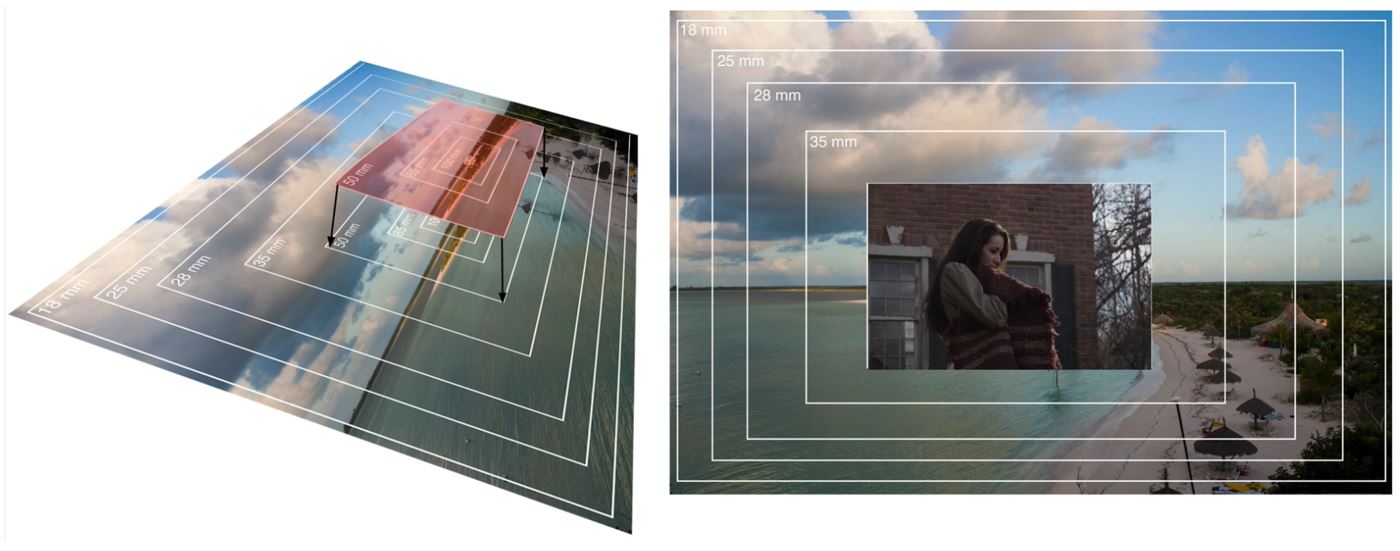
Imagine that you are standing at the top of a hill with a tripod-mounted camera locked onto this view.
Your camera has a lens with a focal range of 18mm down to 100mm.
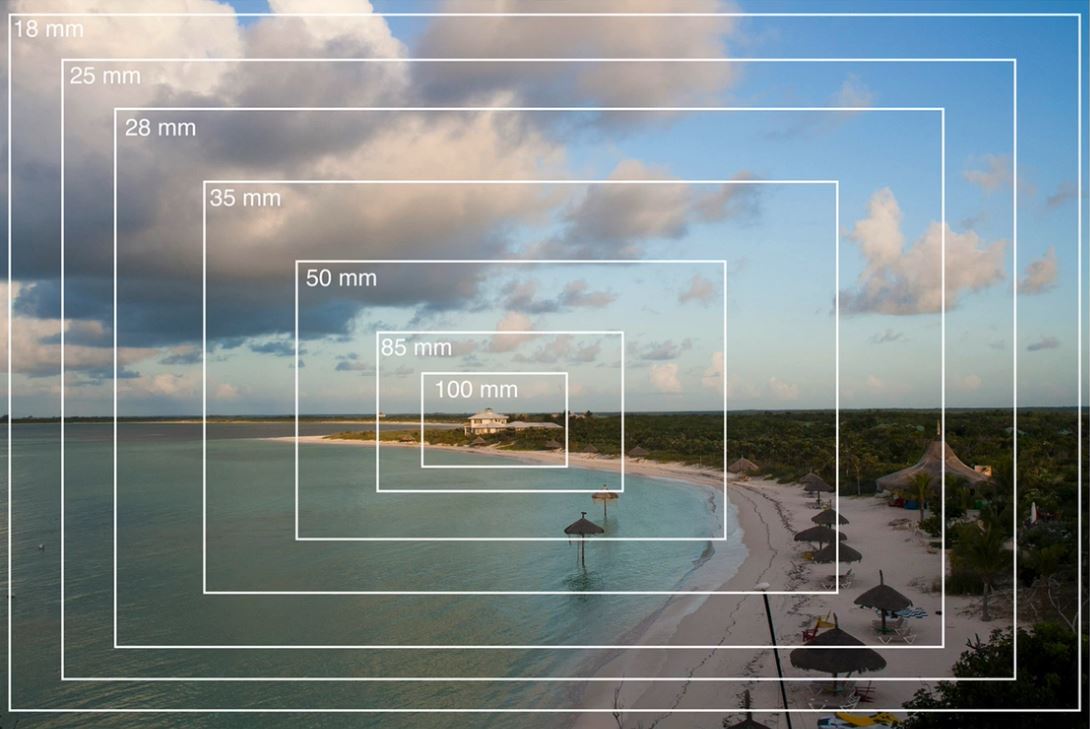
You can now take a photograph at each incremental step, from 18mm all the way down to 100mm.
Take the shot captured at a focal length of 50mm. You would be able to shrink it down and lay it over the widest shot in the set, which in this case is 18mm, and the image would line up exactly
The premise here is that, if we know the focal length for our shot, we can open up the focal length and paint whatever I want into the area (arrowed) and it will line up perfectly with the plate
So let’s consider the workflow and the calculations required.
Calculating Resolution from the Focal Length
We will assume that we have this plate open in Nuke and we now want to take it into Photoshop and paint our house extension over the top.
The plate was shot at a focal length of 35mm and at a resolution of 2048 x 1080.
Let’s say that we have determined that changing the focal length to 30mm will provide the extra space to add in our matte painting.
We need to work out what the new resolution for the shot will be, if we reduce the focal length from 35mm to 30mm.

This can be established using relatively simple mathematical calculations.
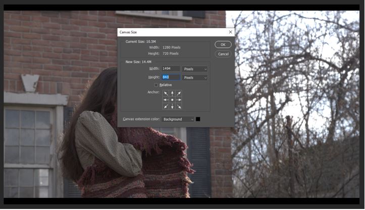
First we calculate the difference between the original focal length and the new focal length. We can find this by dividing the original with the new:
35 / 30 = 1.166666666666667
We can then multiply this value with the original width and original height of the shot:
1.166666666666667 x 1280 = 1,493.333333333333
However, because an image size cannot work in percentage points when dealing with pixels, this value will need to be rounded up, in this case to 1494
We can then use the same equation to calculate the height:
1.166666666666667 x 720 = 840
Again, if this had presented a percentage value, this would also need to be rounded up. However, in this case, it returned a whole integer value of 840 so this does not need any rounding.
To apply this, we can render an image from Nuke at the point in the timecode designated as the optimum projection frame. We can then open this image in Photoshop and increase the canvas size to the new width and height values.
We can then use this new canvas area to create the matte painting.
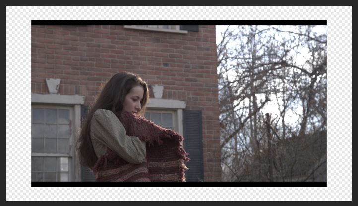
Finally, we can import the completed matte painting back into the Nuke project and composite it behind the original plate footage.
The video below) highlights a problem with this method. When we toggle between the plate and the matte painting, we can see a slight, but nevertheless noticeable shift in the pixels. This is a consequence of rounding the width and height values
The following video provides a full demonstration of the workflow required to execute this method within Nuke. The Overscan error is identified and highlighted at the end of the video.
Calculating Focal Length from the Resolution
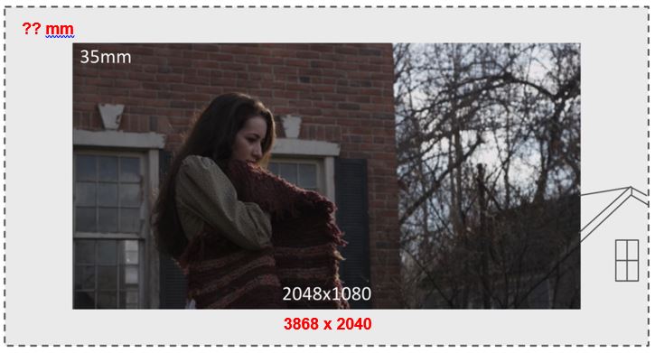
Alternatively, let’s say we have used Nuke to generate an image from the plate, at the projection frame. For this example we will say that the native resolution of the plate is 2k (or 2048 x 1080).
Now, in Photoshop, we have opened up the canvas to 3868 x 2040, which we determined would give us sufficient space to complete the paint work.
We need to work out what the new focal length will need to be, based on the new resolution of our image.
Again this can be established using relatively simple mathematical calculations.
First we calculate the difference between the original resolution and the new resolution, as determined by width and height values.
The original resolution is 2048 x 1080 and the new resolution is 3868 x 2040
Starting with the width the calculation is
1280 / 3868 = 0.5294725956566701
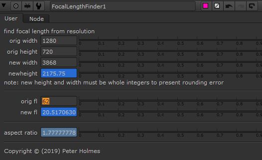
We can now multiply this value by the original focal length, which we established was 62
0.5294725956566701 x 62 = 32.82730093071355
This is our new focal length.
To apply this, we can render an image from Nuke at the point in the timecode designated as the optimum projection frame. We can then open this image in Photoshop and increase the canvas size to the new width and height values.
The following video provides a full demonstration of the workflow required to execute this method within Nuke.
During testing, seen at the end of the video, there is no apparent pixel shift. The assumption for this is that, because we started, in Photoshop, with ‘whole integer’ values for the width and height of the image, there are no rounding up errors associated with the resolution.
Moreover, whilst the new focal length has percentages, rather than a whole value, it is computed as an optic value as opposed to a pixel value. The software is therefore able to accommodate it without any need to round the value up or down.
It would therefore be easy to conclude that this method (calculating focal length from resolution) is the more accurate method and should be favoured over the other method (calculating resolution from focal length).
The Invisible Rounding Error
The basis for this is that, because we created our canvas width and height in Photoshop using whole integers, that there are no rounding errors associated with this method.
To argue that this method does not result in any rounding would be incorrect. This is because Photoshop is actually calculating the image aspect ratio behind the scenes and this also results in some rounding up.
To understand this, we must be familiar with image aspect ratio and how this works.
The height of an image with landscape orientation is defined with a value of 1
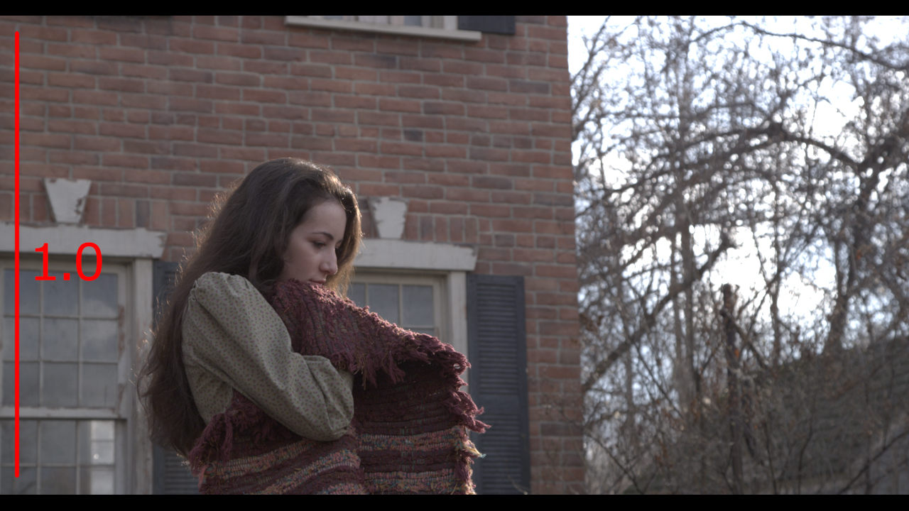
A totally square image (equal width and height) would have an aspect ratio of 1.0
However, because we usually work in landscape format, the width is greater that the height. Therefore the height ratio of 1 is used to calculate the additional ratio of the width.
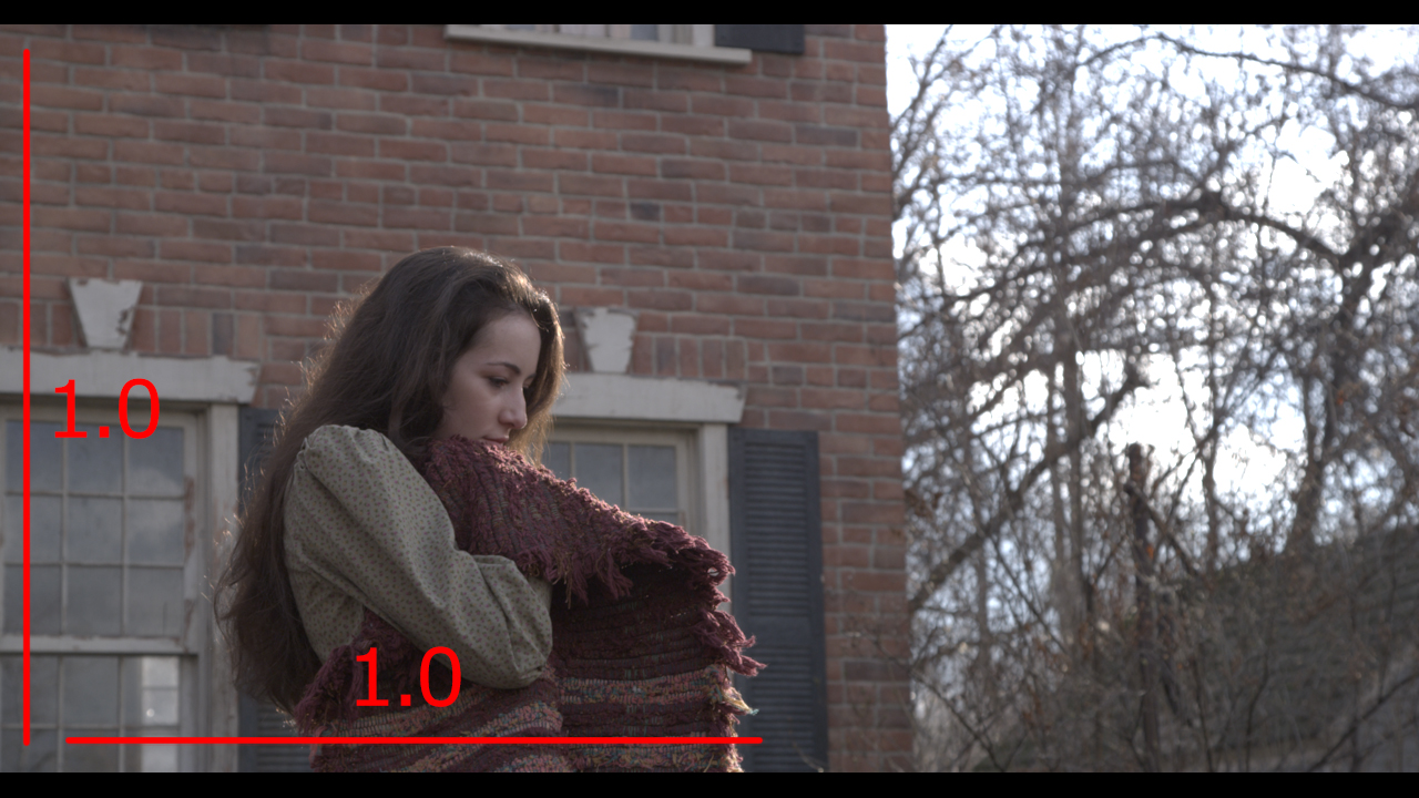
This is a simple equation of width divided by height
To establish the difference between the known value (height), and the new value (width)
In this case the value is 0.77778
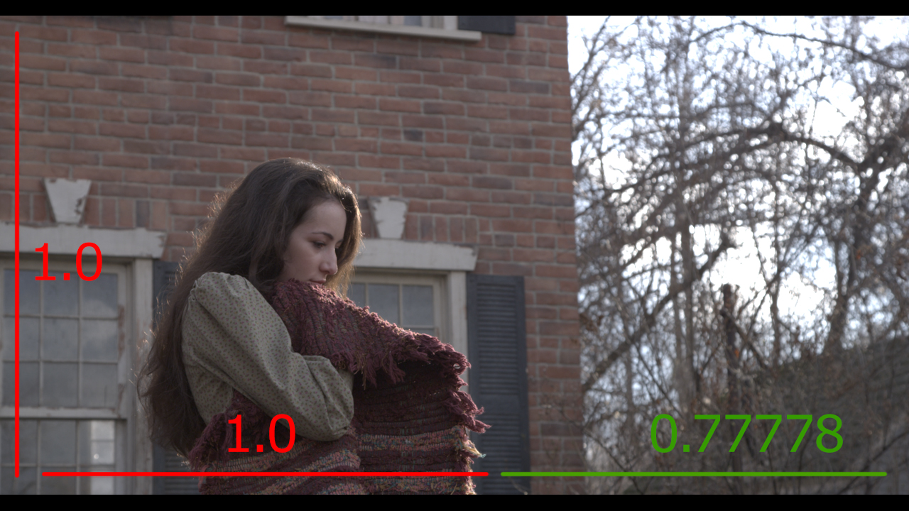
The difference (0.77778) is added to the square (1.0) value resulting in an aspect ratio of 1.77778.
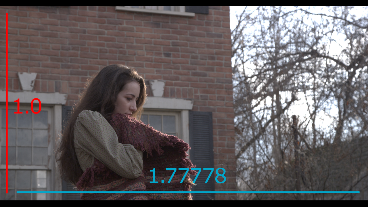
Once Photoshop has established this, the image can be scaled up and down and, providing the width and height values have been constrained, this 1.77778 ratio will always be the same.
However, unbeknown to most Photoshop users, the software actually rounds up changes to the width and/or height to whole integer values.
This is clearly helpful for most activities undertaken in Photoshop. However, for the matte painter, this introduces small mathematical errors which can be disruptive, especially when performing Overscan techniques.
The following video provides a short demonstration of this taking place in Photoshop
A Focal Length Tool
I have been investigating ways to make working out the Overscan values easier and quicker to calculate.
I also wanted to find a way to fix the Overscan issue, which is apparent, especially when calculating the resolution from focal length.
Attributes we Know
I have listed the attributes we always know when starting this process
Original Width
Original Height
Original Focal Length
Attributes we Need
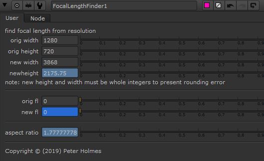
Of particular interest are the three attributes (below) as my intention was for the tool to generate these values automatically.
Aspect Ratio
New Focal Length
New Width
New Height
Aspect Ratio
My investigation into how Photoshop uses the image aspect ratio this attribute to allow images to be re-sized, without affecting the width to height proportions, suggested that it would be necessary to establish this.
Moreover this can be established from known values, using a simple equation:
Original width / original height
New Height
I found the equation to establish the new height a little more complicated, given that the calculation requires the new width as a known value.
The logic was to establish the the new width, then establish the difference between the original width and original height, then multiply the new width by this value.
The expression is written like this:
newwidth / (orgwidth / orgheight)
Again Note how the parentheses allow us to create a formula inside a formula.
In this case we need to establish a value (new width) that is currently unknown.
We can see that, if we type an arbitrary value into the ‘new width’ field, the new height is calculated.
New Focal Length
The logic was to establish the difference between the original and the new width, and then multiply this value by the original focal length.
The expression is written like this:
(orgwidth / newwidth) * orgfl
Again this needs a value (new width) which is currently unknow but, providing a value has been typed into the ‘new width’ and ‘original focal length’ fields, then the ‘new focal length’ value is calculated.
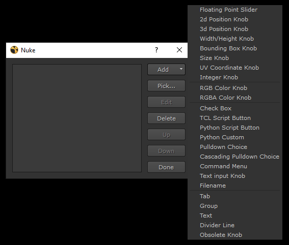
Construction of the Tool
User Controls
To begin, a NoOp node was created. This is similar to a Null and serves only as a element on which the custom tool can be created.
When this is converted to a Group, Nuke applies an input and output node. This means that, once the tool is converted to a Gizmo, it will have an input and output pipe, so can be connected to a larger node tree. I tend to always create Gizmo’s in thes way, even through, in this case, I do not envisage a need to connect it to other nodes.
we can then right click over the properties for the Group node and choose ‘manage user knobs’. This gives us access to all the tools needed to build a custom tool with adjustable attributes.
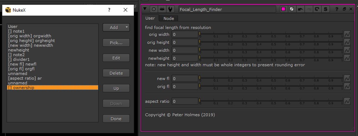
Once a tool, with the preferred tool type is selected, we give the attribute a name. This serves as a variable, allowing us to reference the attribute in expressions.
We can also add a label name, which allows a more human readable description, once it is added to the tool panel.
Here we can see the tools created on the left, and how these appear in the node property. Note the presence of text descriptors and dividers to organise the interface and provide guidance to the user.
Expressions
Once the input tool has been created we can easily add an expression to the field.
I started by typing the known values into the inputs. This gives the equations some initial values to work with and provides a means of checking as the expressions are written.
Then we right click into the field input box and, in the dialogue, choose ‘add expression’.
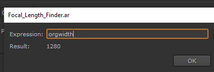
We can then input the expression. I started by typing the name of the tool (which acts like a variable name) and, if this is correct, the value inputted into the box, will appear as a result. If this presents an error, either the variable name is incorrect or there is an error in the syntax.
This shows construction of the expression to reveal the aspect ratio.
Here we see the original width variable is entered, the value typed into the text box is returned as a result.
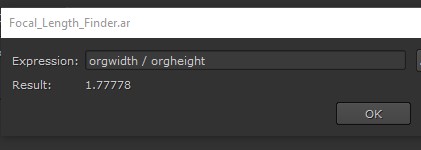
We use the / operator to divide the original width by the original height. See how the value is returned so we know the expression is working correctly.
The expressions for all three attributes, in the tool, were applied in exactly the same way.
Conversion to Gizmo and Installation
Once the tool is constructed, it can be converted to a Gizmo. This is a simple export option in the Group node property panel. I have covered this previously (see the CheckMate tool) so I won’t go into detail here.
To summarise, the Gizmo can then be installed onto any local computer with Nuke installed.
A Python script can be used to create a means of selecting the tool from a menu in Nuke.
The following video provides a detailed demonstration of how I constructed the tool
Using the Focal Length Tool to Fix Rounding Errors
During preparation of the focal length finder tool, it was necessary to test the equations.
The following is a short video showing how I fixed the rounding errors, evident in both scenarios, using the tool.
I was able to satisfy myself the tool will be able to fix a variety of rounding errors and was worth the time and effort used to construct it.
Focal Length and Lens Distortion
Perspective distortion is a warping or transformation of an object and its surrounding area that differs significantly from what the object would look like with a normal focal length, due to the relative scale of nearby and distant features.
Perspective distortion is determined by the relative distances at which the image is captured and viewed, and is due to the angle of view of the image (as captured) being either wider or narrower than the angle of view at which the image is viewed, hence the apparent relative distances differing from what is expected.
https://en.wikipedia.org/wiki/Perspective_distortion_(photography)
This simple and lazily acquired, explanation does suggest that there are further implications when using focal length for Overscanning? If we widen the focal length too far, we risk introducing perspective distortion into our matte painting. If this is the case then, as a consequence, we this being detected when the matte painting is composited with a plate, and other images, that have no perspective distortion, or a different type or amount of distortion.
This suggests that there is a balance between Overscanning and use of additional projections. If we try to extend the projection, from a single camera, by too great an amount, then the more we risk introducing distorted images.
However, if we avoid the use of Overscan in our workflow, then we will need to use way more projection cameras in order to achieve coverage. By doing this, we create further, potentially unnecessary, work and introduce the risk of error arising from blending additional projections together.
I suspect that establishing the balance between using more Overscan and fewer projections, or less Overscan and more projections, will need to be established on a shot by shot basis.
Overscan by Reformatting the Image Area
Up to this point, my focus has been on generating Overscan using focal length.
Adjusting the focal length changes the parameters of the projection camera so it no longer mirrors the shot camera.
My next investigation concerns the creation of Overscan by reformatting the image area. This is essentially a compositing workflow that transcends matte painting and camera projection.
Whilst I believe this workflow to be widely held within the visual effects community, I feel there is some justification in exploring it as an alternative to creating Overscan with focal length and undertaking some comparison. My primary justification is that the method does not change the characteristics of the projection camera and therefore creates fewer variables. This can reduce some of the issues associated with resolution and focal length and also offer some specific advantages.
One point for caution is that this method is very much contained within the compositing application so, if the matte painter is confident that the projection can be undertaken entirely from within Nuke, then this would be a viable approach.
Conversely the creation of Overscan using focal length is something that can be done in any of the previously stated software package and, because they all carry tools and properties for aspect ratio, resolution and focal length, any Overscan generated in this way will transfer accurately between these packages.
As previously stated, I am familiar with the concept and methodology associated with this method is workflow and am practiced in its application within Nuke. However I felt that some experimentation was necessary as I had never used this as part of an approach to Overscanning and camera projection.
My investigations discovered two specific flavours. The fist keeps the plate central in the canvas so the Overscan occurs in equal proportions around the top, bottom, left and right.

The advantage of this method is that it has a central anchor point so will automatically align to the centre of the screen area when composited behind the plate.
The disadvantage of this method is that the image potentially has a lot of pixel data that will never be seen and therefore contributes unnecessarily to the computation, processing and file sizes.
The second allows the Overscan region to be distributed unevenly around the top, bottom, left and right. The advantage here is that the actual area of Overscan can be placed to suit the movement of the shot camera thereby reducing the size of the matte painting and minimising the computation burden.

Both methods exploit Nuke’s ability to retain pixel information beyond the size of the display, in an area known as the ‘bounding box’, but hide this data until it is needed.

Centrally Aligned
The logic is that, when we bring our oversized Matte painting file back into Nuke, we have tp reformat the matte painting image back down to the native resolution. This would scale the image down from its actual size (plate plus Overscan area) down to 1280 x 720.
However, in order to retain the pixels in the bounding box, we set the ‘resize type’ attribute to ‘none’.
Here we see the composite image with the play-head moved to frame 1. This reveals a section of the grid pattern, from the bounding box, filling the space left as the camera pans down.

So Nuke has the ability to retain pixel information beyond the size of the display, but hide it them until it is needed.
Non-Centrally Aligned
The logic with the method is to offset the plate inside the matte painting area so there is more space in the canvas specifically where it is needed.
In the example, used in the demonstration, the shot only camera pans down so there is no requirement for any additional canvas to the left, right or bottom of the plate.
I started by raising the canvas width and height by 100 with the anchor point set to ‘centre’. This means that I know there is exactly 50 pixels on all sides and also gives a small amount of canvas in case there is minor additional coverage needed (i.e. in the event of a small camera shake.)
I then performed a second change to increase the height of the canvas. However this time I changed the anchor point to bottom-centre so all the additional real estate would be added above the plate.

The logic for bringing the Matte painting into the Nuke composite is almost identical. We still have to reformat the matte painting image back down to the native resolution and set the resize type to ‘none’ to retain the pixels in the bounding box.
This method requires us to disable the ‘centre’ attribute in the ‘resize type’ property. This causes Nuke to abandon the centre point of the screen as its anchor point and switch to the default (bottom-left) anchor point instead.

We can then simply add a Transform node and translate the screen area into position.
Because a 50 pixel border was applied to the left, right and bottom, we can simply translate by those exact values to line up the image in the screen area.

The following video provides a demonstration of both methods being applied in Nuke
To conclude, the workflow utilises common Nuke nodes and properties that I believe to be widely held within the visual effects community.
However my investigation found these to be useful for applying Overscan and had the specific advantage of not affecting the characteristics of the projection camera, which is synonymous with approaches involving manipulation with focal length and the potential for rounding errors.
The methods are specific to Nuke so could not be used if the larger workflow required the user to transfer back and forth between applications (i.e. Nuke to Maya and back). If the matte painter was confident that they could complete the full shot from within Nuke and that such a round trip would not be necessary, then then this is a viable choice of workflow.
This would then cease to be a limitation. Moreover the method proved to be faster, more flexible and more efficient.
I found the first method could be achieved relatively quickly and with very few operations, whereas the second required a few more steps to execute but offered tangible efficiency benefits.
The advantage of being able to offset the plate within the Overscan area allows the matte painter to place the real estate only where actual matte painting is needed, thereby reducing the overall project file size and the amount of time spent previewing and rendering the shot.
Overscan with Aperture
I wanted to explore a third workflow for creating Overscan involving adjustment to the aperture of the projection camera.
The following video demonstrates the principle that, by increasing the aperture size of the projection camera, that magnification of the image is achieved.
This is consistent with my understanding of a physical camera insofar as a lens with a larger numerical aperture will be able to visualise finer details than a lens with a smaller numerical aperture. The effect will therefore be an increase in the magnification and the numerical aperture of the objective reduces the working distance, i.e. the distance between front lens and the subject.
The principle here is that we can create Overscan, simply by changing the values in the ‘horizontal’ and ‘vertical aperture’ attributes of the projection camera.
For example, I used an operator to increase the value by 1.32. This was applied to both horizontal and vertical aperture attributes.
36 * 1.32 = 47.52
24 * 1.32 = 31.68

This same value can then be applied to the matte painting to generate the Overscan. To do this I generated an image from frame 50 of the plate, to serve as the basis for the matte painting, and applied a reformat node to it.
However, instead of reformatting by ‘format’, we reformat by ‘scale’. Here the scale value is set to the same value (1.32) which was used to increase the aperture.

The ‘resize type’ attribute is also set to ‘none’ to make use of the pixel data inside the bounding box.
Because, in this scenario, the amount of Overscan would be applied equally to all sides of the plate, we need to make sure the ‘centre’ checkbox is enabled to anchor the image centre to the screen centre.

We have to disable the Crop attribute in the Project3D node. Otherwise the Overscan region is excluded from processing and cannot be accessed.

This shows the extra image area projected onto the card. It is currently smearing because it is outside the image area but will be fine when it enters within the bounds.
We could now go into Photoshop, load our plate image from frame 50, increase the canvas to 1485 x 835 and begin to build the matte painting.

The following is a short video in which I demonstrate application of this technique.
The experimentation undertaken in preparation for recording the video suggests that this is possibly the quickest and simplest of the three methods to execute.

[…] Link to earlier blog entry […]
LikeLike
[…] two main attributes adjusted to optimise a camera projection, I built a tool for use in Nuke. Click here to jump to the post in which the topic is thoroughly interrogated and the construction of the tool […]
LikeLike